Networking in Docker
Docker's default networking model (on Linux) is based on local host bridging via a native Linux bridge (usually called docker0), with each Docker container being assigned a virtual interface connected to the bridge and mapped (via Linux namespaces) to a local eth0 interface in the container which is assigned an IP address from the bridge's subnet.
The host typically does not have routing enabled, and therefore containers are usually only accessible locally within the host. To expose a service running inside a container, a mapping is created between a unique listening port on the host and the container's IP and service port. In order for containers running on different hosts to communicate with each other in a meaningful way, a lot of manual configuration and maintenance of these port mappings is required, or some form of dynamic orchestration is needed, such as that provided as part of Kubernetes.
Networking in Kubernetes
In Kubernetes, one or more containers may be grouped together to form a pod.
- In addition to the individual "application" containers, a special "pod" container is created which owns the networking namespace and pod logical interface.
- The application containers then share this namespace using Docker's namespace sharing function (the "--net=container:<id>" parameter on a "docker run").
- The application containers can communicate with one another simply by using loopback connections.
Kubernetes itself does not dictate any specific networking architecture for the connectivity between pods within the Kubernetes cluster. Instead it defines some general principles which must be adhered to for Kubernetes to function.
- Kubernetes pods should be able to communicate with other Kubernetes pods on the same host or on a different host without requiring NAT.
- Every host (node) in a Kubernetes cluster should be able to communicate with Kubernetes pods on the local or remote hosts, again without requiring NAT.
- Every Kubernetes pod should be directly addressable with the same IP address that it sees itself as having.
These principles obviate the need for management of port mappings for communication between pods running on different nodes and simplifies things from an application perspective.
There are a number of different networking solutions which can deliver on the above principles, e.g. Cilium, Contrail, Weave, Flannel, Nuage, Calico or Open vSwitch (OVS) as well as some basic Linux bridge/router options.
Kubernetes supports a formal interface for cluster networking through a plugin system. This provides a defined interaction between the orchestration in container services for Kubernetes and the networking solution. This is currently in alpha as of Kubernetes 1.8, but a number of plugins are already available (and supported by RedHat for use in OpenShift).
As there are many different networking options available with Kubernetes, it is easiest to pick one well-defined example for the purposes of illustration.
For the remainder of this document, we will consider a specific Kubernetes-based platform and its associated networking stack, namely OpenShift with its default networking plugin based on Open vSwitch.
Networking in OpenShift using OVS
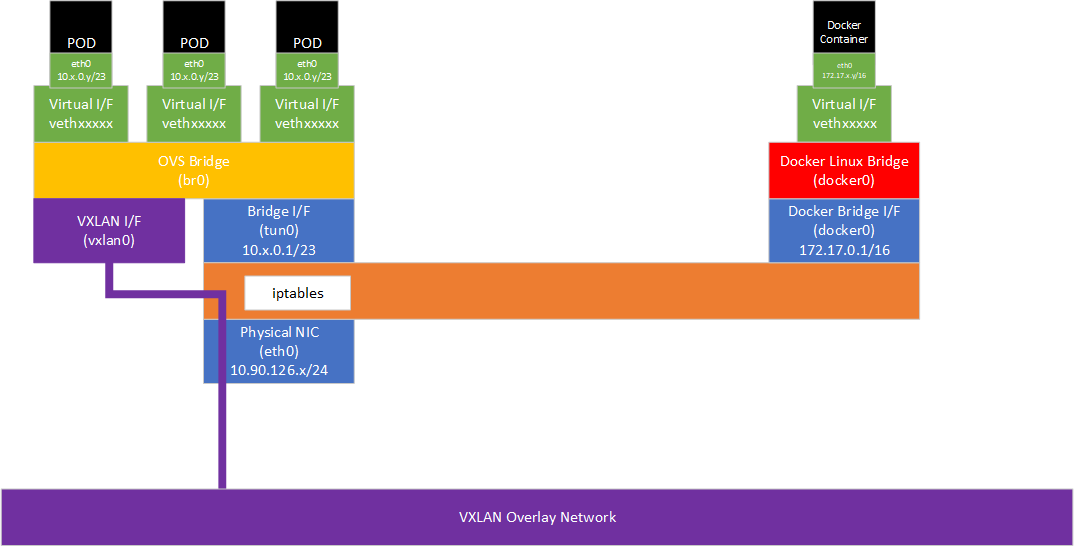
The diagram below shows the default networking topology for an OpenShift node, as provided by Open vSwitch (OVS) and using VXLAN as an overlay network between nodes in the cluster. The general principles here and specifically the kube-proxy iptables implementation also apply to Kubernetes or OpenShift with a non-OVS network plugin, but the exact forwarding behavior between the host network and the local and remote pods may be different.

On a OpenShift node, the standard Docker local host networking is also present, but is only used for Docker Containers created independently of K8S/OpenShift. This consists of a Linux Bridge (docker0) and a non-routable subnet (usually 172.17.0.0/16). Containers are given a virtual interface (vethxxxxx) in a per-container Linux namespace which is mapped to a logical interface (e.g. eth0) inside the container. Typically, traffic is forwarded into the container via iptables DNAT rules based on destination port matching.
The Kubernetes pods similarly use namespaces and logical interfaces inside each pod - in this case the logical interfaces are mapped to virtual interfaces on an OVS bridge (br0).
These namespaces are not accessible through the "ip netns" command (by design, neither Docker nor Kubernetes creates the necessary symlinks to allow "ip netns" to work), but they can be accessed using "nsenter" and specifying the process ID of the container, e.g.:
PID=$(docker inspect --format '' <ContainerID>)nsenter -t ${PID} -n ip addr
For example:
docker ps
| CONTAINER ID | IMAGE | COMMAND | CREATED | STATUS | PORTS | NAMES |
| d1d59528d95e | avinetworks/server-os | "/bin/server.sh" | 5 weeks ago | Up 5 weeks | k8s_avitest.7fc2d0c2_avitest-2-qdc0z_rc-test-01_3b4acf34-a1d4-11e7-8be8-005056b0ec8b_08c78a19 |
PID=$(docker inspect --format '' d1d59528d95e)
nsenter -t ${PID} -n ip addr1: lo: <LOOPBACK,UP,LOWER_UP> mtu 65536 qdisc noqueue state UNKNOWN qlen 1 link/loopback 00:00:00:00:00:00 brd 00:00:00:00:00:00 inet 127.0.0.1/8 scope host lo valid_lft forever preferred_lft forever inet6 ::1/128 scope host valid_lft forever preferred_lft forever3: eth0@if10: <BROADCAST,MULTICAST,UP,LOWER_UP> mtu 1450 qdisc noqueue state UP link/ether ba:c9:ea:b9:bd:79 brd ff:ff:ff:ff:ff:ff link-netnsid 0 inet 10.128.0.180/23 scope global eth0 valid_lft forever preferred_lft forever inet6 fe80::b8c9:eaff:feb9:bd79/64 scope link valid_lft forever preferred_lft forever
nsenter -t ${PID} -n route -nKernel IP routing table
| Destination | Gateway | Genmask | Flags | Metric | Ref | Use | Iface |
| 0.0.0.0 | 10.128.0.1 | 0.0.0.0 | UG | 0 | 0 | 0 | eth0 |
| 10.128.0.0 | 0.0.0.0 | 255.255.254.0 | U | 0 | 0 | 0 | eth0 |
| 10.128.0.0 | 0.0.0.0 | 255.252.0.0 | U | 0 | 0 | 0 | eth0 |
| 224.0.0.0 | 0.0.0.0 | 240.0.0.0 | U | 0 | 0 | 0 | eth0 |
To allow a pod to be accessible across the entire cluster, OpenShift makes use (by default) of an OVS VXLAN-based SDN overlay. The overall IP space is large, for example 10.128.0.0/14. Each node is then allocated a subnet from this range (by default a /23). The first address in the allocation is assigned to the tun0 interface and is used as the default gateway for the pods running on that node. The pods themselves will each be assigned an IP address from the allocation.
[Note: In OpenShift, there are two OVS network plugins, ovs-subnet and ovs-multitenant. This former provides a flat network with no isolation while the latter provides project/tenant isolation by allocating a virtual network ID (VNID) and preventing traffic flowing from a pod in one project/VNID to a pod or service in another project/VNID. Other than this additional VNID-based filtering inside OVS, operation is the same for both plugins.]
From a routing perspective, the entire 10.128.0.0/14 subnet is configured to be directly routable both from the node and from within a pod. So either will simply ARP for any IP in the 10.128.0.0/14 network - reachability is either local via OVS, or remote via OVS and the VXLAN SDN to OVS on a remote node. Any communication to networks other than the 10.128.0.0/14 subnet will be via the pod's default gateway, which is the tun0 interface on the local node.
The routing table within a pod is shown above. The main routing table on the node itself looks like this:
route -nKernel IP routing table
| Destination | Gateway | Genmask | Flags | Metric | Ref | Use | Iface |
| 0.0.0.0 | 10.90.126.1 | 0.0.0.0 | UG | 100 | 0 | 0 | ens32 |
| 10.90.126.0 | 0.0.0.0 | 255.255.255.0 | U | 100 | 0 | 0 | ens32 |
| 10.128.0.0 | 0.0.0.0 | 255.252.0.0 | U | 0 | 0 | 0 | tun0 |
| 172.17.0.0 | 0.0.0.0 | 255.252.0.0 | U | 0 | 0 | 0 | docker0 |
| 172.30.0.0 | 0.0.0.0 | 255.252.0.0 | U | 0 | 0 | 0 | tun0 |
OpenShift (and K8S) Services
When an OpenShift/K8S service is created, it is assigned a cluster IP address from the configured cluster subnet (by default 172.30.0.0/16). kube-proxy on each node then creates iptables NAT rules to forward traffic sent to the service cluster IP on to the individual pods that are the target of the service (whether they be on the local node or on a remote node reachable over the SDN).
[Note: At least this is the default behaviour starting with Kubernetes 1.2 - prior to this, kube-proxy worked as a userspace load-balancer rather than utilising iptables - in future an in-kernel kube-proxy mode will be available, "IP Virtual Server" or "ipvs", which doesn't rely on iptables and therefore scales much higher - this is in alpha as of Kubernetes 1.9.]
For example, supposing there is a service with cluster IP 172.30.64.12 on port 80 targeting four pods with IP addresses/ports 10.128.0.180:8080, 10.128.0.221:8080, 10.129.0.221:8080, 10.130.0.203:8080, then the following iptables rules will be created in the nat table (the KUBE-SERVICES chain is jumped to from the default PREROUTING chain).
The first rule matches on the cluster IP and port and jumps to the chain KUBE-SVC-HDUG4H6TX6XBJH4I:
-A KUBE-SERVICES -d 172.30.64.12/32 -p tcp -m comment --comment "namespace1/service1:http cluster IP" -m tcp --dport 80 -j KUBE-SVC-HDUG4H6TX6XBJH4I |
This chain then splits the traffic evenly across the four pods using the iptables "random" mode. The first rule matches 25% of the traffic, the second matches 33% of the traffic which didn't match the first rule (=25% of the total traffic), the third matches 50% of the traffic which didn't match either of the first two rules (again =25% of the total traffic) and the fourth matches the remaining traffic (again =25% of the total). Each of these rules jumps to a unique chain (KUBE-SEP-xxxxxxxxxxx).
-A KUBE-SVC-HDUG4H6TX6XBJH4I -m comment --comment "namespace1/service1:http" -m statistic --mode random --probability 0.25000000000 -j KUBE-SEP-XGOXOEG4KIB43JUY-A KUBE-SVC-HDUG4H6TX6XBJH4I -m comment --comment "namespace1/service1:http" -m statistic --mode random --probability 0.33332999982 -j KUBE-SEP-4IP36FQPQSENQEUV-A KUBE-SVC-HDUG4H6TX6XBJH4I -m comment --comment "namespace1/service1:http" -m statistic --mode random --probability 0.50000000000 -j KUBE-SEP-3MOSY7OV2XQOPPWU-A KUBE-SVC-HDUG4H6TX6XBJH4I -m comment --comment "namespace1/service1:http" -j KUBE-SEP-SP4YQLIJLYBLSBK5 |
The four unique KUBE-SEP-xxxxxx chains then DNAT traffic to the target pod IP address and port:
-A KUBE-SEP-XGOXOEG4KIB43JUY -p tcp -m comment --comment "namespace1/service1:http" -m tcp -j DNAT --to-destination 10.128.0.180:8080-A KUBE-SEP-4IP36FQPQSENQEUV -p tcp -m comment --comment "namespace1/service1:http" -m tcp -j DNAT --to-destination 10.128.0.221:8080-A KUBE-SEP-3MOSY7OV2XQOPPWU -p tcp -m comment --comment "namespace1/service1:http" -m tcp -j DNAT --to-destination 10.129.0.221:8080-A KUBE-SEP-SP4YQLIJLYBLSBK5 -p tcp -m comment --comment "namespace1/service1:http" -m tcp -j DNAT --to-destination 10.130.0.203:8080 |
kube-proxy therefore configures iptables to act as a basic equal-weight random load-balancer, adding and removing rules and changing probabilities as needed when pods are added or removed.
Any attempt to route traffic to the cluster IP from outside of the OpenShift environment will be dropped by an iptables DROP rule.
So the traffic flow for "east-west" service traffic from a pod (e.g. with IP 10.128.0.100) to the cluster IP is as follows:
- 10.128.0.100->172.30.64.12:80 - forwarded to pod's default gateway (10.128.0.1, the tun0 interface on the local node) through OVS.
- iptables NAT PREROUTING rules which jump through the KUBE-SERVICES chain.
- iptables KUBE-SERVICES chain matches on the cluster IP and destination port and jump through the KUBE-SVC-xxxx chain.
- iptables KUBE-SVC-xxxx chain selects one KUBE-SEP-xxxxx chain based on random choice.
- iptables KUBE-SEP-xxxx rule DNATs to a pod IP (somewhere in the 10.128.0.0/14 range) which may be on the local node or a remote node.
- Routing table lookup occurs and traffic is forwarded back through the tun0 interface as a local route (i.e. an ARP will be performed for the destination).
- iptables POSTROUTING rule causes the traffic to be masqueraded (SNAT) behind this node's tun0 interface address (i.e. 10.128.0.1) - this is needed to ensure reply packets come back through iptables (to have the cluster IP -> target pod IP DNAT reversed).
- If the destination pod happens to be on the local node, OVS will simply bridge the packet to the pod's virtual interface; if it is on a remote node, the packet will be sent over the SDN (via VXLAN encapsulation) to the target node which will end up inside OVS on the target node and then again be bridged to the target pod's virtual interface.
Additional Service Types
The above is the behavior for a service defined with a service spec type of "ClusterIP" (or if no service spec type is present, as "ClusterIP" is the default).
If the service spec type is "NodePort" then, in addition to the above rules for forwarding traffic inside the cluster, further rules are added to expose the service to the outside world via a unique service port. All nodes will receive traffic on this service port, which will be in a configurable range (default is 30000-32767 allowing 2768 services in total in the cluster).
apiVersion: v1kind: Servicemetadata: labels: svc: service2 name: service2spec: ports: - name: http port: 80 protocol: TCP targetPort: http selector: name: webservice type: NodePortoc get service
| NAME | CLUSTER-IP | EXTERNAL-IP | PORT(S) | AGE |
| service3 | 172.30.202.46 | <nodes> | 80:30902/TCP | 9m |
kube-proxy will add iptables rules as follows to forward traffic sent to the node's IP address and node port (in this case 30902) to the Cluster IP:
-A KUBE-NODEPORTS -p tcp -m comment --comment "namespace1/service2:http" -m tcp --dport 30902 -j KUBE-MARK-MASQ-A KUBE-NODEPORTS -p tcp -m comment --comment "namespace1/service2:http" -m tcp --dport 30902 -j KUBE-SVC-BBCPTK7I6HB4WUO4 |
The first rule ensures traffic is SNATted so that the replies from the target pod (which may be on a different node) flow back through the original ingress node to allow proper connection tracking to function. The second rule load-balances traffic using the existing DNAT chain created for the cluster IP.
If the service spec type is "LoadBalancer" then, in addition to the above rules for ClusterIP and NodePort, additional rules are added to expose the service to a load balancer in a supported cloud platform, for example Google or AWS. For example, a service configured as follows results in an exposed service with an external cluster IP address, allocated (by default) from the network 172.29.0.0/16:
apiVersion: v1kind: Servicemetadata: labels: svc: service3 name: service3spec: ports: - name: http port: 80 protocol: TCP targetPort: http selector: name: webservice type: LoadBalanceroc get service
| NAME | CLUSTER-IP | EXTERNAL-IP | PORT(S) | AGE |
| service3 | 172.30.136.130 | 172.29.157.72,172.29.157.72 | 80:31335/TCP | 9m |
Additional iptables rules are then added by kube-proxy as follows on every node:
-A KUBE-SERVICES -d 172.29.157.72/32 -p tcp -m comment --comment "namespace1/service3:http external IP" -m tcp --dport 80 -j KUBE-MARK-MASQ-A KUBE-SERVICES -d 172.29.157.72/32 -p tcp -m comment --comment "namespace1/service3:http external IP" -m tcp --dport 80 -m physdev ! --physdev-is-in -m addrtype ! --src-type LOCAL -j KUBE-SVC-2WB5XSLT4L4KHVX5-A KUBE-SERVICES -d 172.29.157.72/32 -p tcp -m comment --comment "namespace1/service3:http external IP" -m tcp --dport 80 -m addrtype --dst-type LOCAL -j KUBE-SVC-2WB5XSLT4L4KHVX5-A KUBE-SERVICES -d 172.29.157.72/32 -p tcp -m comment --comment "namespace1/service3:http loadbalancer IP" -m tcp --dport 80 -j KUBE-FW-2WB5XSLT4L4KHVX5 |
The first rule marks traffic destined for the external cluster IP so that it will be masqueraded (source NATted) behind the local IP address of the node receiving the traffic. This ensures that replies from the target pod, which may be on a different node, flow back through the original node.
The subsequent rules essentially result in traffic being passed into the same iptables chain as used for the cluster IP load-balancing. The reason there are three rules is down to quirks of the different supported cloud platforms and a feature supported in GCE, GKE and AWS to allow firewalling based on source IP ranges.
Adding the Avi SE to OpenShift
The Avi SE can be deployed to provide pod to service communication (east-west service traffic) and also expose services to the outside world via an externally-routable VIP (north-south traffic).
For east-west traffic, the Avi SE therefore provides a parallel function to kube-proxy's iptables rules but with Avi's full set of load-balancing functionality rather than the basic randomised load-balancing provided by kube-proxy. Avi Vantage can be configured to use its own unique subnet for service IP addresses for east-west services with Avi IPAM allocating service IP addresses from this subnet - in this configuration kube-proxy is still present and functional, but unused with Avi providing a parallel service. Alternatively, Avi can replace kube-proxy's functionality completely and use the same cluster IP subnet as configured in Kubernetes (by default 172.18.0.0/16) - in this configuration, the Avi VIP for each service will match the cluster IP allocated to the service by Kubernetes.
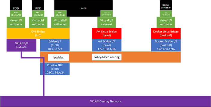
Avi SE deployed using SSH to each node
When the Avi SE is deployed using SSH, it runs as a Docker Container, started by a standard system service and completely outside of the control of K8S/OpenShift. The SE container also has the default Docker networking disabled. We therefore have neither a virtual interface connected to OVS nor a virtual interface connected to the docker0 bridge.
A new Linux bridge (bravi) is created. The subnet used for the bridge is configurable in the cloud configuration - here we are using 172.18.0.0/16 - the local node will be given the first address and the SE will be given the second IP address.
North-south Avi Virtual Services will be allocated VIPs either on the same subnet as the nodes (e.g. 10.90.126.0/24 in this example) or on a different subnet (or subnets) if BGP is used.
When traffic for the VIP enters the node, policy-based routing is used to forward the traffic to the SE. For the east-west IPAM subnet and the individual east-west and north-south VIPs, policy-based routing rules are provisioned by the SE onto its host as follows:ip rule0: from all lookup local32755: from all to 10.90.126.213 lookup avi32756: from all to 10.90.126.214 lookup avi32757: from all to 10.90.126.211 lookup avi32758: from all to 10.90.126.212 lookup avi32759: from all to 172.25.1.2 lookup avi32760: from all to 172.25.1.6 lookup avi32761: from all to 172.25.1.3 lookup avi32762: from all to 172.25.1.1 lookup avi32763: from all to 172.25.1.4 lookup avi32764: from all to 172.25.1.5 lookup avi32765: from all to 172.25.0.0/16 lookup avi32766: from all lookup main32767: from all lookup default
ip route show table avi10.90.126.211 via 172.18.0.2 dev bravi metric 353410.90.126.212 via 172.18.0.2 dev bravi metric 353410.90.126.213 via 172.18.0.2 dev bravi metric 353410.90.126.214 via 172.18.0.2 dev bravi metric 3534172.25.1.1 via 172.18.0.2 dev bravi metric 3534172.25.1.2 via 172.18.0.2 dev bravi metric 3534172.25.1.3 via 172.18.0.2 dev bravi metric 3534172.25.1.4 via 172.18.0.2 dev bravi metric 3534172.25.1.5 via 172.18.0.2 dev bravi metric 3534172.25.1.6 via 172.18.0.2 dev bravi metric 3534
In the case of native scale-out, a route as added only on the node running the primary SE for that VS. With BGP scale-out, a route is added on every node where the VS is placed. The nodes where a route for a VIP exists will respond to ARP requests for the VIP via proxy ARP.
iptables nat rules are added on the host to allow masquerading of traffic from the SE. Outbound BGP connections from the SE hit this masquerade rule and therefore the BGP peering appears to be with the node IP address. Load-balanced traffic to pods is SNATted by the SE to its local Avi bridge interface address (e.g. 172.18.0.2), so this is what will appear in the Avi logs as the source IP for the back-end connection. However, when the traffic is forwarded to a pod from the Avi bridge to OVS, it will hit an iptables masquerade rule which will SNAT the traffic again behind the OVS tun0 interface IP. Pods therefore receive traffic sourced from the tun0 interface on the node of the SE that handled the connection (exactly as they do when kube-proxy is used).
For BGP and BFD to operate correctly with different router implementations, as of Avi Vantage 17.2.4, iptables mangle rules are automatically created to ensure the TTL in packets matches what is required for single-hop BGP/BFD:
-A PREROUTING -p tcp -m tcp --sport 179 -m ttl --ttl-eq 1 -j TTL --ttl-set 2-A POSTROUTING -p udp -m udp --dport 3784 -j TTL --ttl-set 255
For BFD to operate, an iptables DNAT rule is added to forward BFD packets sent by an external router to the node address into the SE:
-A PREROUTING ! -s 172.18.0.2/32 -p udp -m udp --dport 3784 -j DNAT --to-destination 172.18.0.2:3784 |
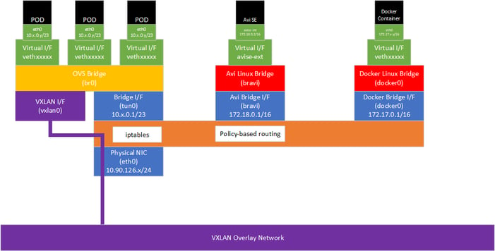
Avi SE deployed via Kubernetes Daemonsets
When Avi SE is deployed using Kubernetes Daemonsets, the SE will be connected both to the bravi bridge and the OVS bridge:
The default route points via the eth0/tun0 interface, but routes to the local node subnet and to any configured BGP peer routers are sent through the Avi bridge to ensure BGP/BFD traffic matches the iptables mangle and nat rules configured on the host.Kernel IP routing table
| Destination | Gateway | Genmask | Flags | Metric | Ref | Use | Iface |
| 0.0.0.0 | 10.128.0.1 | 0.0.0.0 | UG | 0 | 0 | 0 | eth0 |
| 10.90.126.0 | 172.18.0.1 | 255.255.255.0 | UG | 30000 | 0 | 0 | avise-int |
| 10.90.126.199 | 172.18.0.1 | 255.255.255.255 | UGH | 0 | 0 | 0 | avise-int |
| 10.128.0.0 | 0.0.0.0 | 255.255.254.0 | U | 0 | 0 | 0 | eth0 |
| 10.128.0.0 | 0.0.0.0 | 255.252.0.0 | U | 0 | 0 | 0 | eth0 |
| 172.18.0.0 | 0.0.0.0 | 255.255.0.0 | U | 0 | 0 | 0 | avise-int |
| 224.0.0.0 | 0.0.0.0 | 240.0.0.0 | U | 0 | 0 | 0 | eth0 |